SolarCADby CADDEZ
Built for utility-scale solar

From a site boundary to a buildable, costed layout — in minutes.

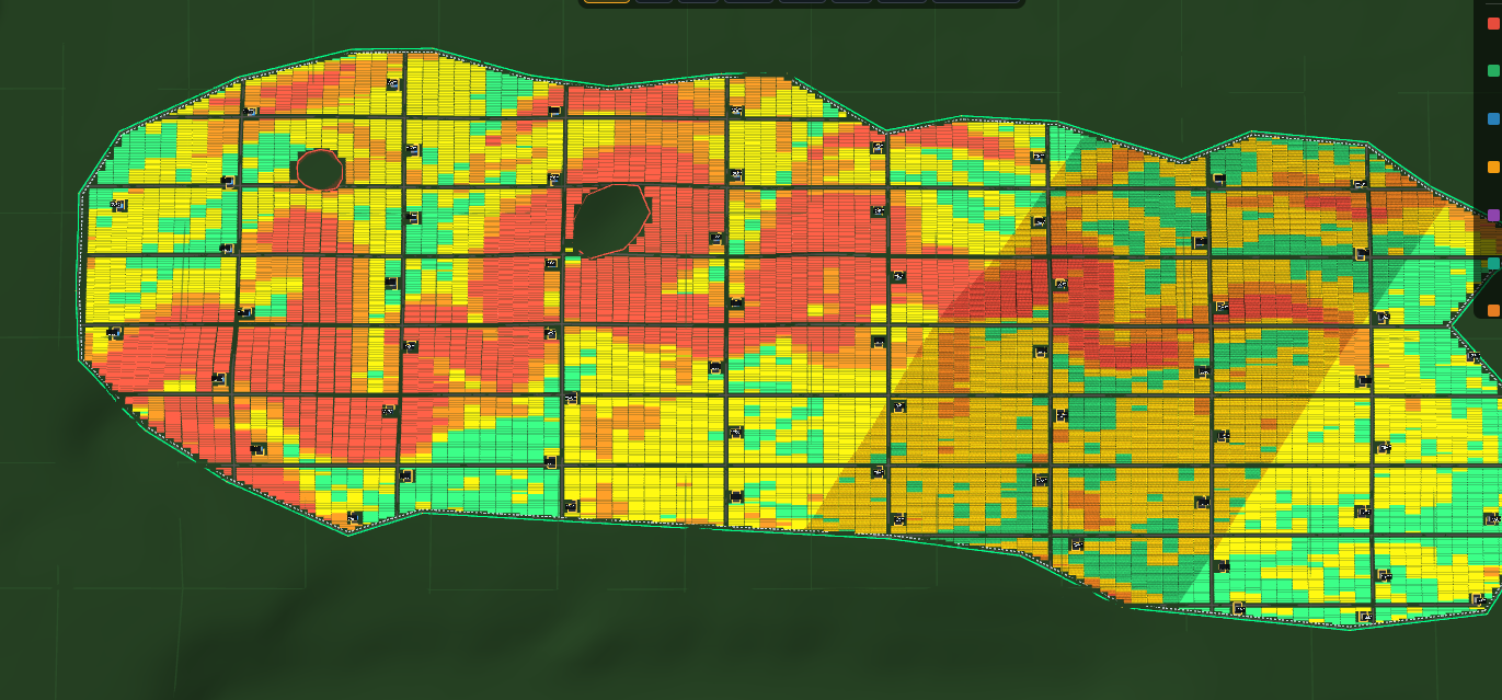
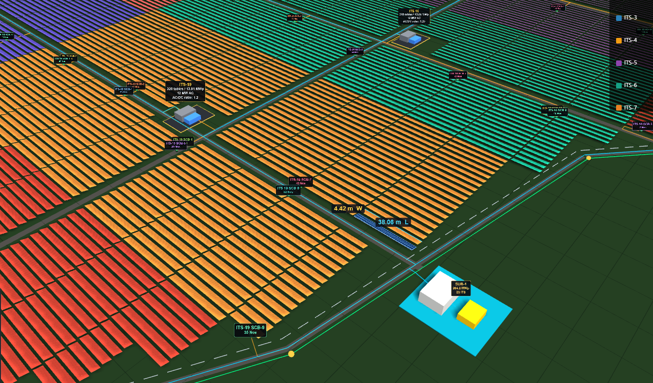
SolarCAD places every table or tracker inside your boundary, groups them into ITS stations, positions the string combiner boxes, routes the cabling along roads and trenches, pools the substations, and hands you a DXF drawing set and a bill of quantities. The kind of work that takes a design engineer days.

Sign in See it on your own site Access is invite-only while we onboard our first projects.
Add public/images/hero-layout.png — a filled plant in top view

Everything a layout needs, in one pass

Not a rooftop tool. SolarCAD is built for ground-mount plants where the hard part is not drawing panels — it is the grouping, the cabling and the quantities.

Placement that respects the site

Fixed tilt or trackers, full and half tables, road grids, periphery ring road, setbacks and no-table zones. Rows are held strictly inside the boundary, including concave corners.

Electrical design, not just geometry

ITS grouping to your AC capacity, SCB placement packed to your strings-per-box limit, and cabling routed along roads and trenches — never across a table.

Quantities you can price

An Excel workbook down to per-ITS, per-SCB and per-table detail, with cable lengths taken from the routes actually drawn, not estimated.

Real terrain

Import a DEM, georeferenced against your KML site. Slope banding shows what is buildable; drop everything above a threshold and see the capacity cost immediately.

Shadow analysis

The 21 December, 9am–3pm criterion: the window your row pitch actually achieves, the pitch it needs, and which rows your ITS stations and substations shade.

Several parcels, one plant

Import multiple boundaries and lay each out independently, with substations pooling across parcels and cabling routed between them.
How it works

Four steps. The whole loop is fast enough to try three layouts before lunch.

  1. Bring in the siteImport a DXF (with your layer names) or a KML/KMZ, or draw the boundary. Exclusion zones and survey geometry come with it.
  2. Set the system and fillModule, orientation, strings, tilt, row pitch, road grid. Press Fill and the plant appears with its capacity.
  3. Add the electrical designITS stations, SCBs, cabling and substations. Drag a station and everything downstream re-routes and re-costs.
  4. ExportA layered DXF for the drawing set and an Excel BOQ for the estimator.

What you hand over

Output your drawing office and your estimator can use directly.

DXF drawing

Boundary, exclusion zones, setback, internal and periphery roads, every table or tracker on its own ITS layer, SCB boxes with tags, ITS stations, substations, cable runs and slope bands — each on a named layer you can freeze and thaw.

Excel bill of quantities

Plant summary, per-ITS capacity, per-SCB detail, and a hierarchical ITS → SCB → table sheet with tags, configuration, modules, kWp and cable lengths for every run.

Add public/images/dxf-sample.png — the exported drawing open in CAD

Built for the plants that are hard to lay out

MountingFixed tilt (2P, 4P and other orientations, half tables) and single-axis trackers (1S/2S/3S/4S, mixed on one site)
Site inputDXF with layer mapping · KML / KMZ with true coordinates · drawn by hand · several parcels in one plant
TerrainGeoTIFF DEM, georeferenced to the site · slope banding and exclusion · shadow criterion and equipment shadows
ElectricalITS grouping by AC capacity · SCB packing by strings per box · trench and road cable routing with capacity limits · string home-runs · substation pooling
OutputLayered DXF (R12) · Excel BOQ workbook · cloud projects you can reopen and re-run

What Pro includes

The full feature set, exactly as it appears inside the app.

  • Layout engine — fixed tilt and trackers
  • ITS grouping and SCB placement
  • DXF import with layer mapping
  • DXF export — boundary, roads, tables, SCBs
  • Cable routing in the DXF, with cable quantities
  • Full BOQ workbook — per ITS, per SCB, per table
  • BOQ summary sheet
  • Several parcels in one plant
  • Substations and ITS→substation cabling
  • String (home-run) cables
  • Layout phase optimiser
  • Terrain import — DEM, georeferenced
  • Slope analysis, and dropping steep tables
  • Shadow analysis — row pitch and equipment shadows

A Basic plan is available for smaller plants, with limits on plant size and saved projects. Ask us which fits your work.

See it on one of your own sites

Send us a boundary from a live project and your usual design parameters. We will build the layout with you on a call — your units, your standards — and send you the DXF and the BOQ afterwards. No obligation.